Longitudinal beam diagnostics
Longitudinal Diagnostics for Beam-Based Feedback Systems
Maschine Strahlkontrollen
Longitudinal Diagnostics for Beam-Based Feedback Systems
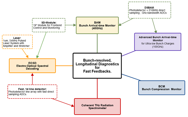
The Special Diagnostics ( SDiag ) team as part of the group MSK deals with development and operation of diagnostics, implemented into beam-based feedback systems for stabilization of longitudinal electron bunch properties.
The diagnostics are installed at the free-electron lasers FLASH and European XFEL.
The instruments are used to measure the following properties:
- Bunch arrival time relative to the femtosecond stable reference, provided by the laser-based synchronization system
- Bunch compression, in terms of THz radiation intensity and is dependent on the integral and width of the charge density within a bunch
- Bunch current profile (envelope)
- Spectral form factor of each electron bunch, which allows to draw conclusions about the charge density profile.
For this purpose, we develop complete devices (mostly 19’’ modules) incorporating optical, electro-optical and electrical components. The entire electronic chain for control, readout and data analysis is developed together with other sub-groups within MSK.

FLASH/EuXFEL
Stable X-ray Free Electron-Laser (FEL) output requires among other parameters precise control of the longitudinal properties of the electron bunches. The longitudinal shape is tailored mainly in the Bunch Compressors (BCs). This is achieved with an accelerating module running off-crest to induce an energy chirp in each electron bunch. A suited energy chirp in combination with an energy-dependent path length through a magnetic chicane results in a longitudinally increased charge density and thus, shortened bunch length.
The specialty about the two X-ray FEL facilities, FLASH and the European XFEL both relying on super-conducting accelerator technology, is the operation in a 10Hz burst mode. Within each 10Hz burst a train of several hundreds of electron bunches with up to few MHz repetition rates are accelerated and shaped in a multi-stage compressing scheme, until reaching final beam energy and peak current.
This 10Hz burst operation opens the possibility for stabilizing bunch parameters within the MHz-rate bunch-trains using real-time capable detectors and a beam-based feedback implementation, which acts on the RF amplitude and RF phase in those acceleration modules prior to the BCs.

In the following sections, the bunch diagnostics suited for usage in beam-based feedback systems are briefly presented.
Brief Portrait : Bunch Arrival-Time Monitor (BAM)
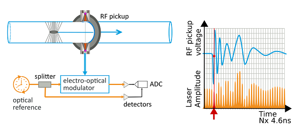
The BAM is a broadband pickup-based arrival-time monitor with electro-optical detection scheme, utilizing a Mach-Zehnder–type electro-optic modulator.
The BAM, as an integral part of the laser-based synchronization system, measures the arrival time with a sub-10 fs time resolution over a large range of bunch charges from 20pC and up to 1nC.

References :
- BAM RF Pickup: http://dx.doi.org/10.1103/PhysRevSTAB.18.012801
- Electro-optical Frontend: http://accelconf.web.cern.ch/FEL2015/papers/tup049.pdf
- BAM Overview: http://accelconf.web.cern.ch/icalepcs2017/papers/tupha125.pdf
Brief Portrait : Bunch Compression Monitor (BCM)
The BCM is a simple and robust monitor, which is composed of a cubic vacuum chamber with an in-vacuum diffraction screen, an in-air optic transport, detectors, pulse-shaping electronics and ADCs for a simple peak-sampling method. The detector type requires additional pile-up and background correction algorithms.
The final signal depends on the absolute charge and the charge density, thus allows for conclusions about the bunch compression rate. The signal generation does not depend on the beam orbit and does not disturb the bunch itself.

References :
Brief Portrait : Electro-Optical Spectral Decoding (EOSD)
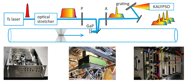
When an ultra-relativistic electron bunch passes an electro-optic crystal within a few millimetres distance, its transient electric field induces a change of birefringence which propagates together with the field through the crystal.
The temporal profile of this transient field, which is equivalent to a half-cycle THz pulse, provides an image of the longitudinal charge distribution inside the electron bunch.
This birefringence can be probed by a co-propagating, chirped optical laser pulse. In combination with a polarizer/analyser setup, a grating spectrometer and a line-detector, the generated intensity modulation of the laser pulse allows for conclusions about the longitudinal profile of the electron bunch. The wavelength chirp is used as time scale.

References :
- Kalypso: https://doi.org/10.1016/j.nima.2018.10.093
- EOSD: http://accelconf.web.cern.ch/ibic2018/papers/weoa03.pdf
- Time-stretch method: http://accelconf.web.cern.ch/fel2019/papers/wep015.pdf
