
URL: https://msk.desy.de/e88987/e88989/index_ger.html
Breadcrumb Navigation
FLASH/XFEL LLRF Field Control
The primary role of the LLRF system is to stabilize the amplitude and phase of high power (HP) 1,3GHz RF field in a superconducting Nb multicell cavity linear accelerator.
Its task is to measure electromagnetic field inside accelerating structures, compare it with a required value, and adjust an output of an RF field source accordingly to ensure required field stability
")
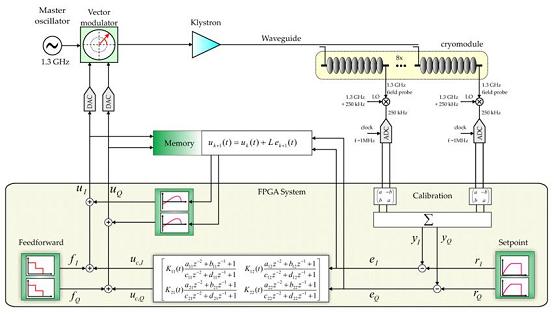
Schematic view of the new LLRF control system
The cavity probe signal (taken from an antenna in each cavity) is converted from the cavity frequency of 1300 MHz to an IF frequency in the range of 10-100 MHz (typically 250 kHZ or 54 MHz are used at DESY). This lower IF still holds the original amplitude and phase information of the field inside the cavity. It now can be digitized with ADCs (typically sampling rates of 1MHz or 81 MHz are used at DESY). Also we try to use very fast ADCs with sampling rates around 500MHz, to direct sample the 1.3 GHz signal without using any IF. The digitized signal now undergoes a digital field detector which extracts the I and Q componentes out of the input stream. We use two different methods here: IQ-sampling and so-called non-IQ-sampling or IF-sampling. The resulting field vector of each cavity is multiplied by a rotation matrix to calibrate amplitude and phase. Finally the field vectors of 8 cavities are summed up (vector sum) for the vector sum of a whole cryomodule, and thouse of 4 cryomodules are summed up to the vector sum of the RF station which is driven by one klystron. The vector sum of the 32 cavity fields represents the total voltage and phase seen by the beam.
This signal now is to be regulated by a control algorithm (feedback) which calculates corrections to the driving signal of the klystron. Herefor we use a setpoint table and the corrections are added to the so-called feed-forward table. It is called feed-forward table because also a feed forward algrithm can be applied to support the regulation.
The measured vector sum is subtracted from the setpoint table and the resulting error signal is amplified and filtered to provide a feedback signal to the vector modulator controlling the incident wave. A feedforward signal is added to correct the averaged repetitive error components. Beam current information (measured by toroids) is used to scale the feedforward table to provide fast feedforward corrections if the beam current varies. The cavity detuning is determined from forward power, reflected power, and probe signal and is used to control the fast piezo tuners to reduce cavity detuning errors to less than a tenth of the cavity bandwidth.
The remaining field fluctuations determine the preformance of the LLRF system, and in the end the field stability determines the beam quality of the accelerator.
Errors in the calibration can also result in residual voltage fluctuations in presence of microphonics while the measured vector sum is held constant. Therefore the quality of the vector sum calibration is essential for LLRF performance.